Machine 24Build a permanent-magnet alternator← → step through the guidestand · 3 studs on a Ø 40 cm circle
Speed0 rpm
3-phase AC0 Hz
DC volts0 V
Current0 A
Charging0 W
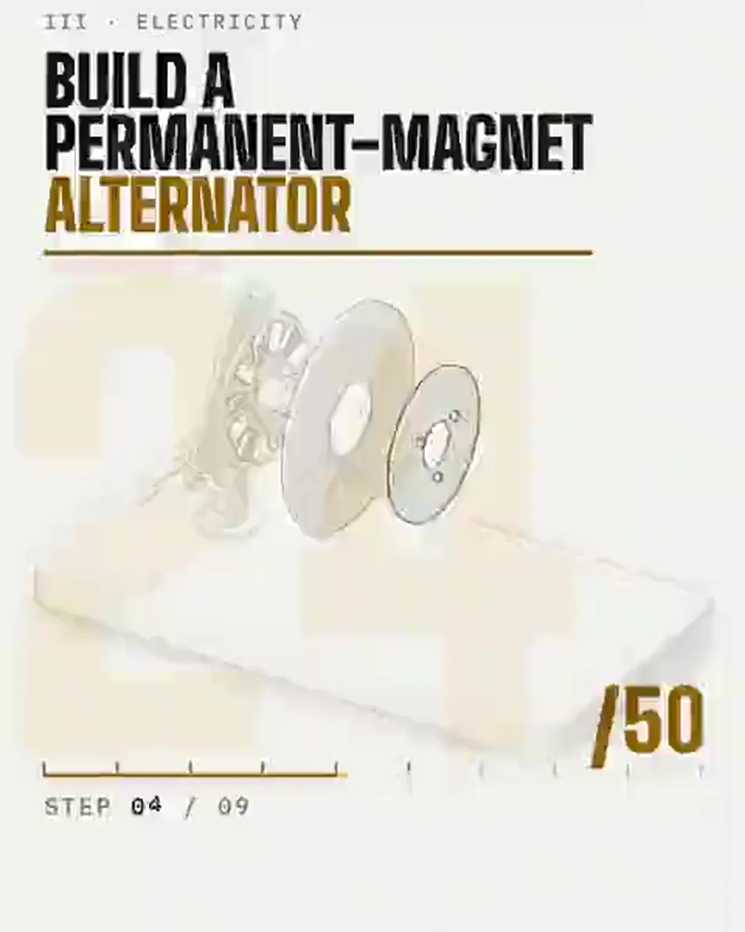
What this step adds; in part B, current leaving the coilsParts already in placeDrawn at 1 unit = 5 mm, twice the scale of the larger machines, so the magnets read; the camera is the usual one. Two 30 cm steel discs each carry 12 magnets 50 × 25 × 12 mm, alternately N and S (the paler faces are N); between them a resin disc holds 9 hand-wound coils, 3 to each of 3 phases. Each coil's voltage rises in step with speed (Faraday's law): here the rectified open-circuit voltage is 0.177 V per rpm, less 1.4 V across the rectifier's diodes. Below 150 rpm that stays under the 24 V bank's 25.2 V and no current flows; above it the EMF drives current through the coils' resistance and reactance: E² = (V_battery + diodes + I·R)² + (I·X)², with X growing with speed. 12 poles make 6 cycles a turn: 42.5 Hz at 425 rpm, where the model is set to give Hugh Piggott's 500 W (18.5 A into 27.0 V). Assumed: the winding (a 150 rpm cut-in, 0.145 Ω per phase or 0.29 Ω line to line, and a reactance of 3.6 Ω at 425 rpm, set to pass through Piggott's figure) and a bank that rises 0.1 V per amp. At full speed the coils then lose about 100 W as heat and the diodes about 26 W, so about 80% of the electrical power reaches the battery. A 3:1 belt from a test motor stands in for the blades or a water wheel, and the rotors are drawn turning at a sixth of their real speed so you can follow them. This is a guide to how the parts go together, not engineering drawings. Neodymium magnets snap together hard enough to break fingers and shatter: handle one at a time, keep them apart with wood, and lower the front rotor only on its jacking screws. Guard the belt and the spinning rotors, and fuse the battery lead.