Machine 49Build a spark-gap radio← → step through the guidetwo boards · 52 × 29 cm each
Keyup
Spark–
Wave–
Coherer–
Relay–
Received–
or hold Space
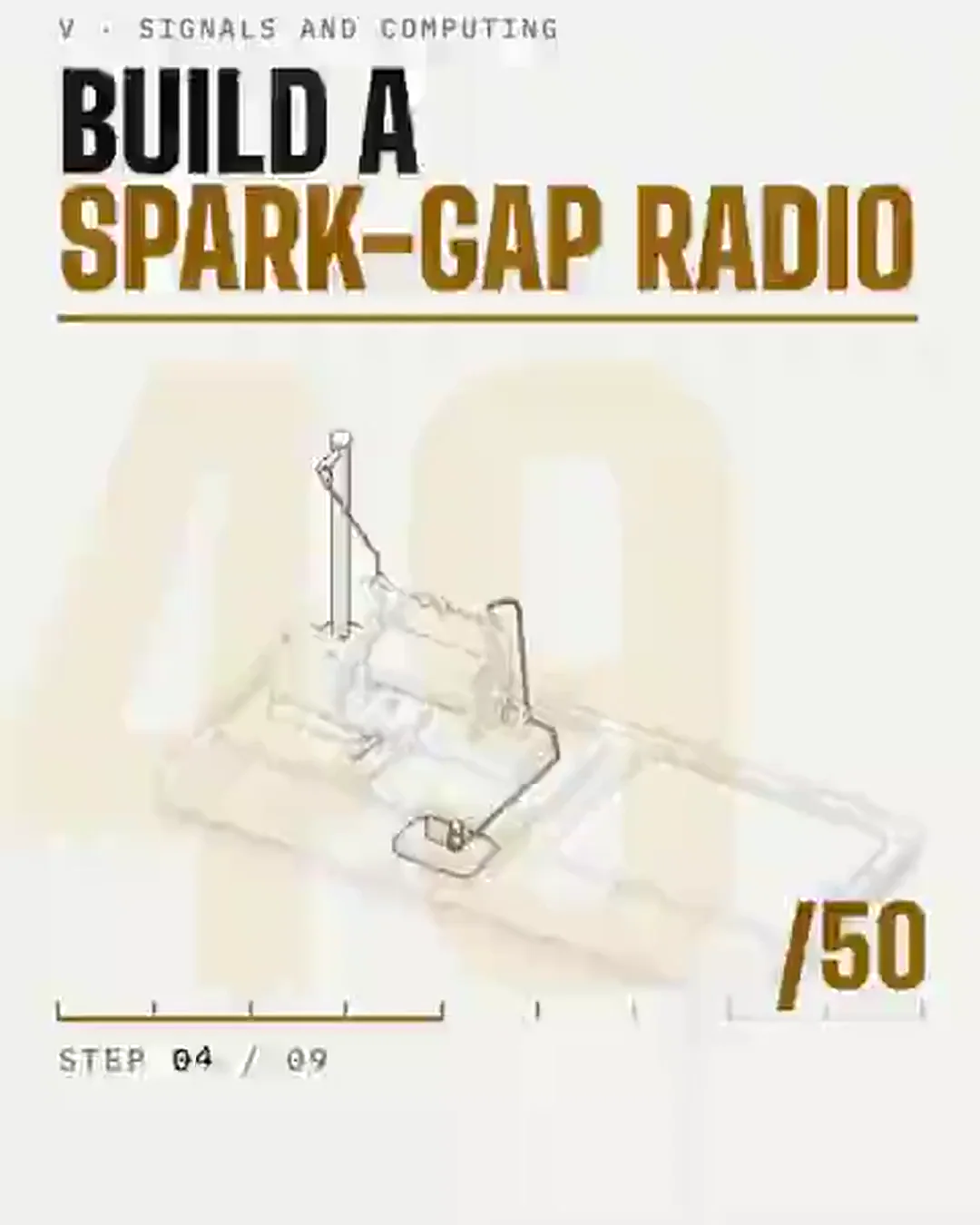
What this step adds; in part B, sparks and live current (the wave ring is a schematic: radio waves are invisible)Parts already in placeA spark transmitter and a coherer receiver of the kind Marconi used, drawn side by side at 1 unit = 5 mm (masts and earths shortened). A 6 V lead-acid battery drives about 4 A through the coil's primary; the hammer break opens it about 40 times a second (as adjusted, assumed), and each break makes the secondary's thousands of turns throw a spark across the 8 mm gap: air breaks down at about 3 kV per mm, so about 24 kV. Each spark rings the aerial at roughly f = c / 4ℓ, about 5 MHz for a 15 m wire, and splatters across the band. At the receiver the wave makes the coherer's filings cling: its resistance falls from several MΩ to several kΩ, so its one cell drives 0.33 mA instead of 0.4 µA through a relay that pulls in at 0.25 mA (assumed); the relay rings the bell from a local battery, and the bell's hammer knocks the tube on its back-stroke to shake the filings loose (Popov's trick, 1895). The ring drawn between the masts is a schematic only: radio waves are invisible and cross 3,500 km in 11.7 ms; here it takes 0.6 s. Morse is sent at 8 words a minute. In December 1901 Marconi's spark-and-coherer link sent the letter S about 3,500 km across the Atlantic. This is a guide to how the parts go together and how the first radio worked, not engineering drawings or an invitation to transmit. A spark transmitter splatters across the whole radio band and is illegal to operate without a licence in most countries; a licensed operator would build it only as an unconnected display or into a shielded dummy load. The induction coil's secondary gives dangerous high-voltage shocks: never touch the rods or balls while the key can be pressed. Keep both aerials clear of power lines and disconnect them before a thunderstorm.